By Pete Vack and Stuart Anderson
Photos courtesy Stuart Anderson
Despite the coming-out of one of the three Talbot Darracq 1500cc Grand Prix cars in the mid 1990s, (see “Classic and Sportscar”, March 1996) there has been very little information available about the powerful, DOHC high tech engine designed by two ex-Fiat employees for the 1926 Grand Prix 1500 cc supercharged formula. The Talbot Darracq featured the first use of an offset driveshaft to allow a lower driver position and a three piece chassis frame of great beauty. But the piece de resistance was the straight-eight roller bearing DOHC supercharged engine.
For the first time, VeloceToday reveals the details of this fascinating and advanced engine, as well as its close relationship with the powerful Fiat 404/405. Our thanks to Stuart Anderson, who spent almost 20 years restoring the only totally intact Talbot Darracq, for his photos, descriptions and help with a unique look at this classic racing engine.
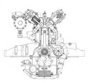
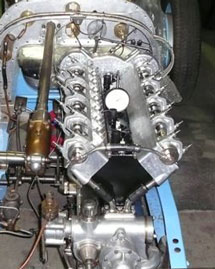
Left, a diagram of the 1926 Fiat 405 engine; at right, the Talbot Darracq.
In 1922, Vincenzo Bertarione and Walter Becchia, fresh from Fiat, came to work for the French-English firm of Sunbeam-Talbot-Darracq (STD). The two designers then created the firm’s immensely successful Sunbeam DOHC six and a 1500cc four, based on existing Fiat engines. STD chief Louis Coatalen then asked the two Italians to draw up a new engine for the 1926 Grand Prix formula; that it would again be similar to the Fiats they had helped design was taken for granted. (For more, read “GP Talbot Darracq: The Races”). Just how much was not known until recently. Alas, the short lived formula–in place for only two years– did not allow STD to fully develop this fascinating engine.
How similar to the Fiat 404/5 was the T-D 8C 1500?
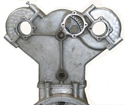
The cam gear cover at the rear of the Talbot
Darracq engine used six spur gears.
Taking it from the top, both engines reverted to a two valve combustion chamber after using four valves per cylinder, but with a significantly larger intake valve (by some 20 percent). The valve angle for the Fiat was 102 degrees, the Talbot 90 degrees. Both used roller bearings and finger type cam followers.
So far, very similar. But as Griff Borgeson wrote in his classic book,
The Classic Twin Cam Engine, “A really major difference existed in the methods of driving the camshafts,” wrote Borgeson, “A highly original Y shaped arrangement of three beveled shafts was used for the Fiat and a classical spur gear train in the Sunbeam.” We know that the T-D 1500 carried on the same spur gear arrangement.
Block, head, combustion chamber construction
The technique used to weld the heads to the forged steel cylinder dated from the 1900s, but the DOHC concept made it a challenge. Borgeson published a rare photo of a cutaway section of the Fiat 404/405 cylinder and head, and we are able to compare it to the Talbot cylinder/head construction. Here the similarities are more than striking.
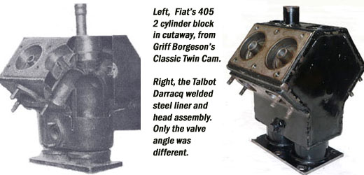
Both engines made use of full length camshaft boxes that were bolted to the four sets of welded heads which were in turn fitted with the combustion chambers/piston cylinders. (see photo below). Obviously, the Fiat influence was very clear. (Tubes coming out of the top of the head are for water pipes or hoses going to the radiator).
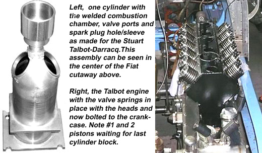
Camshafts are hollow, and each cam lobe drilled so that there is a good supply of oil to the valve gear. Surplus oil spills down through drains front and rear, lubricating the cam drive gears at the rear, and the train of gears for water pump and other ancillaries at front. Valves are operated by finger-type cam followers, each individually mounted, so that they can be withdrawn individually for adjustments without disturbing all the rest of the gear, and valve clearance adjustments are made using hardened steel lash-caps of varying thickness.
Crankcase, sump and crankshaft
The great complexity of the crankcase casting was very similar to that of the rival Delage. In this photo, the upper half is on left, lower half on the right. 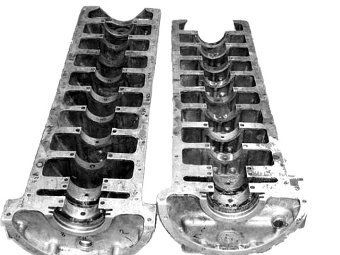
Below is the lower half of the crankcase, veiwed from the underside showing the position of the siamesed oil pumps, pressure and scavenge driven from below the crankshaft, and the position of the large oil gallery pipe which feeds the main and big end bearings. 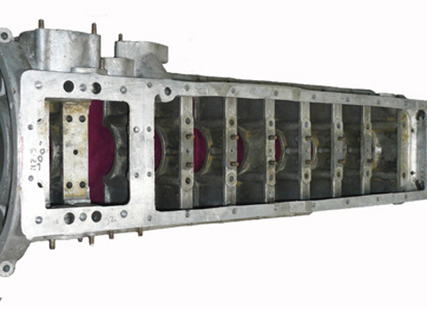
Split roller bearings were relatively new, and used by STD instead of the normal one-piece roller bearings which necessitating a multi-piece crankshaft to accommodate the roller cages. Also seen is the position of the long through-bolts which held the whole lot together, with threaded ends projecting through the upper surface of the upper half to act as locating and holding-down bolts for the 4 cylinder blocks. When assembled, there is virtually a solid cast wall and a bearing each side of each crank throw – almost like eight single cylinder engines in a row.

The original crank before restoration. Note the large center section where the two cranks are bolted together.
The crankshaft is actually two four cylinder crankshafts, joined at 90 degrees to each other, giving a firing order of: 1,5,3,7,4,8,2,6. There are 10 main bearings, the one at the front being a large ball bearing acting as a thrust, the other 9 are all split cage roller bearings, the rear two straddling the crankshaft gear which drives the oil pumps below, and the cam drive above.
Carburetion and Supercharger
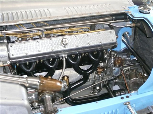
Above, all assembled and ready to run. It only took 20 years…
Note the long intake manifold, another Fiat practice, and how it goes from 8 to 4 and 2 to 1 from the supercharger to the engine. STD did a lot of work on the engine in the winter of 1926-27, changing manifold pressures, diameters, and temperatures, but Anderson thinks that problems may have been with the Solex carburetors. The Australian crew also eliminated cold start reluctance when fuel droplets can tend to fall out of suspension over the long manifold length, by fitting a Kigass pump and pipework. “It is very long and tortuous but in main, works well,” said Anderson.
________________________________________________________________
If you are enjoying this article, why not consider a donation to VeloceToday? Click here for details..it’s easy!
________________________________________________________________
The Talbot Darracq 700 1500/8C GP car Engine Specifications
Straight eight
Construction
Four welded steel blocks consisting of two cylinders each integral with cylinder block
Cylinder heads, steel welded construction integral with cylinders
Domed pistons, 7:1 compression ratio
56mm bore by 75.5mm stroke, total of 1485cc
Power 160 at 7200 rpm
DOHC valve angle 90 degrees
Valve gear triple coil valve springs
Valves Two per cylinder with cam followers
Camshaft case 10 roller bearings
Cam drive, gears driven from rear of engine
Crankcase: two piece cast light alloy split on crankshaft centerline, with shallow oil sump below acting as collector for scavenge pump of dry sump oiling system
Two piece crankshaft, split in middle joined by a large circular flange on each piece, fitting neatly into a step on the other, and secured by a ring of 12 very tight-fitting bolts.
Rod big ends split roller
Roots Supercharger, front driven with Solex Carb
Magneto ignition, Bosch
To those who made it all happen
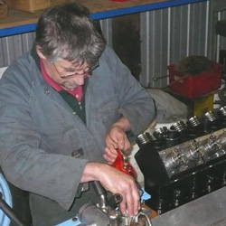
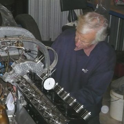
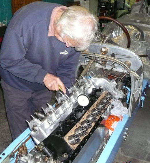
Left engineering genius, Grant Cowie, oiling pistons before we fitted the last of the cylinder blocks. Right, Grant’s assistant Ashley Tracey, checking piston heights with dial gauge.
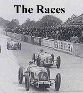
For more about the Grand Prix Talbot Darracq, click on the images.

Another fascinating story.
After just replacing 2 head gaskets on my milano i can appreciate a designer wanting to use monobloc construction, although not for a family car.
My 1959 vintage osca 187 (now a 211) engine had one crank double row ball bearing in #5 position (carries the flywheel/clutch weight) and one roller bearing in #1 position (copes with the chain thrust). the intermediate 3 are conventional babbitt shells. the roller brg is a weak link in this design, as the mileage accumulates the rollers get sloppy & the oil gets dirty leading to eventual broken crank.
The engine also had needle type camshaft bearings in #1 and #3 positions, the center being a conventional iron on aluminum affair wth pressurized oil.
The head and block were mated at birth on a big lapping machine, avoiding the use of a head gasket. i use permatex for sealing, candy poole liked to use rotten string.
The later 187N engine used conventional thin wall crank bearings in all 5 positions.
Jack
Fascinating,what an engineering marvel.
Thank you.
This wonderful vehicle has been sold to a good friend of Stuart Anderson; a local Doctor, who is enjoying numerous competitive outings in the Talbot-Darracq, and who has invested considerable care in addressing a small number of functional issues (such as those arising from recommissioning an 85 year-old GP racer, one of three!). In recent reports, the GP car has been fitted with de-mountable road-gear, so that the doctor can drive it to competitive events!